Quantcast
Channel: Software – Evil Mad Scientist Laboratories
Viewing all 32 articles
Browse latest View live

Vector Snowflake Application

$
0
0

Another snowflake

A new application to draw your own snowflakes and save them in PDF format. Clean, cross-platform, open-source, and able to generate closed-polygon vector shape output. Oh yeah.

If you look around on the web, you’ll find any number of nifty programs to generate paper snowflakes. Some of these are pretty good– like Make-a-Flake and Snowdays which both have a neat interface like cutting a piece of paper. Ze Frank also has a great and very different online appwhere you can draw a flake out of translucent shapes and spin it in 3D.

(As you can see we’re primarily interested in illustrative snowflakes, not anatomically correct or fractal snowflakes, although there is some wonderful crossover.)

So while there are some nice snowflake program out there, we didn’t actually come across any that were both (1) cross platform (2) open-source, and (3) able to export a vector drawing with a closed path. While many of the programs do let you save an image of snowflake design, that’s actually of limited utility. What you really want is a vector drawing so that the design has infinite resolution and is suitable for importing and editing in Inkscape, Corel, Illustrator, and so forth.

That last part is — not coincidentally– interesting because surely everyone with a CNC machine, laser cutter, 3D fabber, vinyl cutter, or so forth would then be able to produce their own snowflakes from the pattern. And there is a growing community of fab labs and online sites like thingiverse where people share patterns for making physical things.
Our program is called “snowflake” (creative, ain’t we?), and you can follow the links at the end of this article to download it. It is written in the Processing development environment which is a wonderfully simple environment for designing cross-platform applications, particularly ones that manipulate graphics.

Once you launch the program, you are presented with a window that looks like this:
Snowflake Screenshots
The initial shape is an overall hexagon, which is generated by taking the editable slice– highlighted here and when you start the program– and reflecting and rotating it to complete the full pattern of the snowflake.

Within the editable slice, you can also see three highlighted control points that can be dragged around. There is control point at every vertex and at the midpoint of every line segment between two vertices.

Snowflake Screenshots
If you drag a control point that is the midpoint of a line segment, it turns that control point into a new vertex. That new vertex also gets new control points at the midpoints to its neighbors.

The two “initial” vertices (from the hexagon) are constrained to stay along their respective radial lines. Every other control point and new vertex can be dragged where ever you like.
At the lower left corner of the window is a “Clear” button that erases your snowflake and restores the initial hexagon. The “Save” button on the other side saves your snowflake as a PDF file. The file is automatically saved in the same folder as the snowflake program, under file name snowflake-####.pdf, where #### is a number.

Snowflake generator   Screenshot of PDF output

Here’s a screenshot of a typical snowflake, along with a screenshot of the corresponding PDF output file. Note that the PDF file just has the outline path of the snowflake saved– it’s ready to use without any extraneous colors or text.

The PDF file is generated directly from the showflake shape that you have drawn. So if you draw a shape with overlapping lines, you will see them in the output file.


Download the snowflake program!
The current version is Snowflake 2.0, uploaded July 22,2009.

Programs written in Processing are called sketches. The snowflake sketch can be either opened and run directly or from within the Processing environment.

Method 1: Download the Snowflake 2.0 application directly for your choice of platform:

  • Linux (1.2 MB .ZIP archive)
  • Mac (1.3 MB .ZIP archive)
  • Windows (1.2 MB .ZIP archive)

Method 2: Download Snowflake 2.0 source code and Processing

  • 2A: Download Processing for your platform.
  • 2B: Download the Snowflake 2.0 sketch file (50 kB .ZIP archive)

Old version (just “Snowflake”) is also still available for download:

Method 1: Download snowflake application directly for your choice of platform:

  • Linux (1.2 MB .ZIP archive)
  • Mac (1.3 MB .ZIP archive)
  • Windows (1.2 MB .ZIP archive)

Method 2: Download source code and Processing

  • 2A: Download Processing for your platform.
  • 2B: Download the snowflake sketch file (32 kB .ZIP archive)

We’re sure you’ll make some interesting snowflake designs, and interesting things from those designs. Let’s see them in the Evil Mad Science Auxiliary!

If you like playing with symmetry, you might also be interested in our SymmetriSketch application.


SymmetriSketch: A simple app for playing with symmetry

$
0
0

We were recently contacted by a mathematics instructor, who suggested that it might be interesting to have a program like Snowflake, but with the option of picking and choosing different symmetry properties.

Natural snowflakes have (approximate) sixfold rotation symmetry plus reflection symmetry. However, a lot of things that you can draw by hand have absolutely no resemblance to snowflakes at all– and it is somewhat fun to explicitly play with the rules.

Our new program, SymmetriSketch, sticks to the same basic design principles as Snowflake: it’s cross platform, open source, and able to export a true vector drawing with a closed path. However, SymmetriSketch is a much more flexible program that allows you to play with different symmetries, and create all kinds of different things that would never be mistaken for frozen water.

Here’s what it looks like when the program first opens:

SymmetriSketch 1

The initial shape is an overall pentagon– an object with five-fold rotation symmetry and reflection symmetry. The figure is generated by taking the editable slice– highlighted here and when you start the program– and reflecting and rotating it to complete the full shape that you see.

Within the editable slice, you can also see three highlighted control points that can be dragged around. There is control point at every vertex and at the midpoint of every line segment between two vertices. If you drag a control point that is the midpoint of a line segment, it turns that control point into a new vertex. That new vertex also gets new control points at the midpoints to its neighbors.

Every vertex point can be moved to any location on the screen with the exception of the vertex that is initially at the top point of the pentagon– that vertex is constrained to move along the vertical axis– the axis of reflection symmetry.

SymmetriSketch 6

The controls are purposefully kept simple. There are two symmetry controls– for the order of rotational symmetry and to toggle reflection– which you can change in the lower left hand corner of the screen.

The number, with its +/- controls, refers to the order of discrete rotational symmetry. If the number shown is n, then n-fold rotational symmetry is applied, which means that the displayed object is unchanged when rotated by 360 degrees/n. In the screenshot above, 9-fold rotational symmetry is applied.

Orders from 1 to 99 are allowed– note that 1-fold rotational symmetry is “no symmetry at all” since it requires 360/1 = 360 degrees of rotation to return to the original shape.

The second control is for reflection symmetry, and toggles between “reflect” or “rot. only,” where it either does, or does not apply a mirror reflection across the vertical axis.

SymmetriSketch 3

With reflection symmetry turned off, the figure is drawn with pure rotational symmetry. (This screenshot was taken while editing the shape, and you can see control points, indicated by little circles.)

Going for higher orders of rotational symmetry can lead to interesting looking shapes as well:

SymmetriSketch

At the lower right corner of the window are “Clear” and “Save” buttons. The “Clear” button that erases your drawing and resets the vertices on the screen. The “Save” button saves your drawing as a PDF file. The file is automatically saved in the same folder as the SymmetriSketch program, with file name SymmetriSketch-####.pdf, where #### is a number.

SymmetriSketch 7   SymmetriSketch 7b

Here is what the PDF output looks like, in comparison to the program that generated it on screen.

The PDF files are saved with single-stroke output. That is to say, any shape drawn by this program can be drawn in one pass, without lifting a pen– although lines are allowed to cross. That makes the program suitable for designing continuous paths for pen plotters, vinyl cutters, engraving machines, and other CNC and art robots.


Download the SymmetriSketch program!
The current version is SymmetriSketch 1.0, uploaded July 22,2009.

Programs written in Processing are called sketches. The SymmetriSketch sketch can be either opened and run directly– as an application– or executed from within the Processing environment.

Method 1: Download the SymmetriSketch application directly for your choice of platform:

  • Linux (1.2 MB .ZIP archive)
  • Mac (1.3 MB .ZIP archive)
  • Windows (1.2 MB .ZIP archive)

Method 2: Download SymmetriSketch source code and Processing

  • 2A: Download Processing for your platform.
  • 2B: Download the SymmetriSketch sketch file (60 kB .ZIP archive)

We suspect that this app will lead to some good geometric play time– and maybe even interesting objects via the vector export. We’d love to see the drawings that you produce in the Evil Mad Science Auxiliary!

PeggyDraw 2

$
0
0

peggydraw2


We are pleased to finally release PeggyDraw 2, a little bit of long-delayed software. It’s a Processing application that you can use to draw simple 1-bit animations on a 25×25 grid. The neat bit, of course, is that you can press the “Save” button, and the file that it saves is actually an Arduino program, ready to be programmed onto a Peggy 2.


You can download PeggyDraw 2 right here. It’s fully built in Processing, so that it works on Mac, Windows, and Linux. Also, open source, designed to be adaptable.
Some things to note about this program:


  • If you don’t have Processing on your computer, download it here.
  • The editing interface is easy point-and-click. Try it out to see how it works.
  • You can individually pick different delay times per frame, as low as 20 ms, or give every frame the same duration.
  • The frame data is stored in Arduino program memory, so you’re only limited by the flash memory in terms of frame number– over 250 frames fit on an ATmega328P.
  • The output file is located in the PeggyDraw2 sketch directory, inside a directory named “PeggyProgram” “data.” The file is called “PeggyProgram.pde.”
  • You can both save a file and later reload it for editing.
  • The formats used in PeggyDraw 2 should be easily adaptable to write sequences for other types of LED grids, even of different aspect ratio and control software.

And, special thanks to Matt Mets, http://cibomahto.com for assistance with Processing.
Update, 3/19/2011: We’ve posted a new version, PeggyDraw 2 v. 1.1, available here. Note that the output file is now stored in the “data” directory, not a separate “PeggyProgram” directory.

StippleGen: Weighted Voronoi stippling and TSP paths in Processing

$
0
0

grace2k-2

One of the perennial problems that we come across in a variety of contexts, including CNC artwork and producing artwork for the Egg-Bot, is the difficulty of creating good-quality toolpaths– i.e., vector artwork representing halftones –when starting from image files.

One of the finest solutions that we’ve ever come across is Adrian Secord’s algorithm, which uses an iterative relaxation process to optimize a weighted Voronoi diagram, producing a set of points (stipples) that can closely approach the appearance of a traditional stipple drawing.

Another important technique is “TSP art,” where the image is represented by a single continuous path. You can generate a path like this by connecting all of the dots in a stipple diagram. Designing a route that visits each dot exactly once is an example of the famous Travelling Salesman Problem (or TSP). From the standpoint of toolpaths (for the Egg bot and most other CNC machines), a “TSP” path is even nicer than stipples, because little or no time is spent raising and lowering the tool.

Today we’re releasing a new program, StippleGen, which can generate stipple diagrams from images, using Secord’s algorithm. StippleGen saves its files as editable, Eggbot-ready Inkscape SVG files, which can in turn be opened by other vector graphics programs, or re-saved as PDF files for use in other contexts. It can also generate a TSP path from the stippled image, and either save that path as an SVG file or simply use that path as the order of plotting for the stipple diagram.

StippleGen is free and open source software, written in the Processing development environment. It comes ready to run on Mac, Windows, and Linux, and it is available for download now.


Other programs

It is worth pointing out, right up front, that our software does not fill a vacuum. StippleGen is not the first, fastest, or most accurate software yet developed to produce stipples or TSP paths. Rather, it is designed to be easy to install, easy to use, and easy to modify. It is capable of producing excellent quality output with up to 10,000 points, when speed is not a primary concern.

While Adrian Secord’s own stippling software is no longer available for download, there are a few other codebases worth of note. In particular, the weighted voronoi stippler at
saliences.com has a Windows executable, and runs as a command-line utility. And there are also a number of fast TSP solvers, including Concorde, which is available with a GUI for Windows.
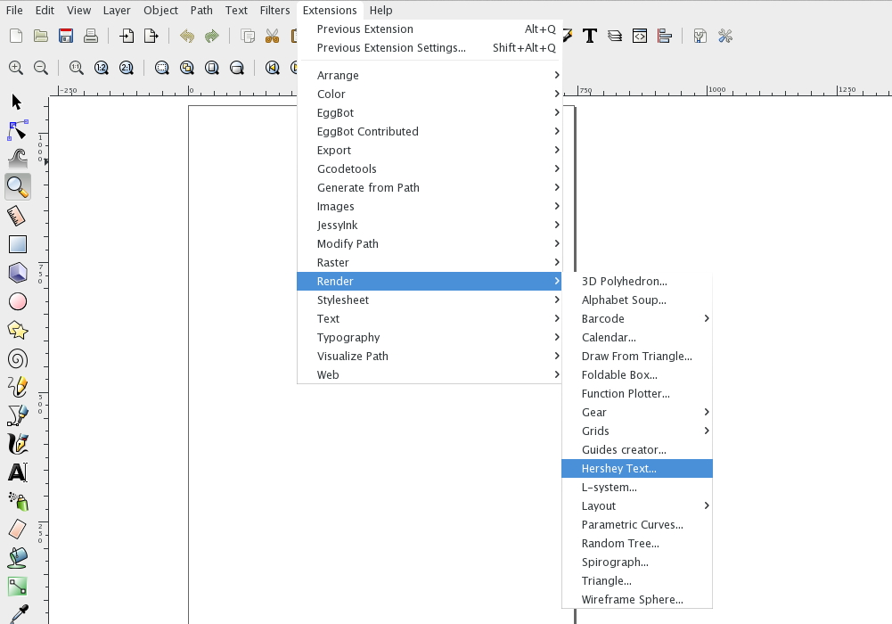
 

StippleGen Controls
grace2k-2

When you first open up StippleGen, you will be presented with this window, which shows the drawing in progress (in the top part) and a set of controls below that.

Rather than present you with a blank screen, StippleGen automatically loads a demo image upon launch, and begins calculating. This way, you can try out the program, even if you don’t have a good image of your own to start with. And, you can stop it at any time by loading a new image.
controlsection

Here is what the control section looks like.

Under the “MASTER” heading, you can press the “Load image file” button to load a new PNG, JPG, or (non-animated) GIF file. There are also buttons for saving either the stipples or the path between them as an SVG file, and a button to quit the program.

Under next heading are options to “Pause” and “Reset.” When you select “Pause,” the program switches from the “running” mode where it optimizes the stipple location, to the “paused” mode, where the stipple positions are fixed, but the program steadily tries to improve the efficiency of a TSP path between the points. “Reset” starts the stipple calculation over from scratch, starting with a new distribution of points.

The bottom heading on the left is the Stipple Count. Changing the value on this slider allows you to set the number of stipples that are displayed. Changing this number will reset the calculation, as a full new set of stipples will be generated. It can take a verylong time to calculate the stipple placement when the number of stipples is large, so increase this number only with care, and if you have patience.

The Display Options can be changed at any time, but only take effect when the next generation of stipples is displayed. Among these options are the minimum dot size (which you may want to decrease if you go to larger numbers of stipples) and the range in size. If the range is set to zero, then all stipple dots will be drawn with the same diameter. There is also a “white cutoff” that can be used to eliminate points in truly white areas of the initial image.

The display options also include the option to view the target image in the background, or to display the network of Voronoi cells as it is optimized. Finally, you can choose to hide (or by default, show) the TSP path while it is being optimized.


Using StippleGen
grace2k_rejectionsampled

When you load a new image, the first pass of calculation begins as a crude set of points generated by rejection sampling. The number of points is controlled by the “Stipple Count” slider. Here, we’re starting with the default, 2000 stipples, and variable dot size.


grace2k_vor
After a few generations, the stipple image begins to take shape. Here, we’ve turned on the Voronoi cell display, so that you can see what that looks like.
grace2k-path

Once you are satisfied with the stipples, you can hit the “Pause” button to begin calculating the plot order, shown by the blue line here. Once that’s satisfactory, you can save the stipples to an SVG file.

grace10k

Here’s another direction to go: 10,000 stipples, instead of 2000. It takes much longer to calculate, but… sometimes, it’s worth it.
plant10kdots

Here is another “demo file”– a corn plant, available for download from this page. This shows 10,000 stipples, with variable stipple size.
plant10k_fixedsize

For comparison, this is what the same 10,000 stipples look like, but with fixed size. We’ve also turned on the white cutoff, so that there’s less detail away from the main plant.
plant10kpath_start

When we first click the “Pause” button after letting our stipples settle, we’re presented with this mess: the path between the stipples. The blue line represents the path that a plotter would take naturally between the points. As you can imagine, nearly all of the time drawing would actually be spent moving between points.
plant10kpath_nocutoff2

By letting this run for just a few moments, StippleGen creates a “nearest neighbor” path– a first guess at a decent solution to our travelling salesman problem. We’ve momentarily turned down the dot size so that you can see it a little better.

As you can see, there is a lot less blue on the screen here– this would plot muchfaster. One other thing to notice is that while the rare “background” dots don’t make much of a difference to the overall picture when looking at stipples, the paths between those dots at the edges are actually pretty distracting. We can invoke the “white cutoff” slider one more time to fix that, though:


plant10k_readyforsaving

Here now, we have a pretty good candidate file, reasonably well optimized.

We have now adjusted the dot sizes (both minimum and range) so that the stipples themselves are pleasing. We’ve also allowed enough time for the path to look okay for the TSP file. There area couple of stray stragglers– longer than necessary path segments that might correct themselves given time. But for the most part, it’s all good enough.

At this point, we can save SVG files– one of each, as a stipple file, and one as a TSP path.
fileoutplant_small

fileout_tsp_small

Opening up the two SVG files in Inkscape, we can see the stipple file (top) and TSP file (bottom).


fileout_plant

fileout_circles

The “stipple” file is made up of many (10,000 to be specific) unfilled circles, grouped together for efficient handling in Inkscape. They’re ready to be plotted to an Eggbot or to be exported (for example) to a toolpath generator. Those circle sizes could also control hole depth with a cone-shaped wood-carving too, for example.
fileout_tsp_large

fileout_tsp_large_edited

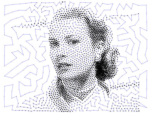
The TSP file is a single, continuous path, consisting of 10,000 nodes. We had just a couple of straggler lines in our final file (top), so we used the path tools in Inkscape to remove the offending segments (below).
StippleGen 1

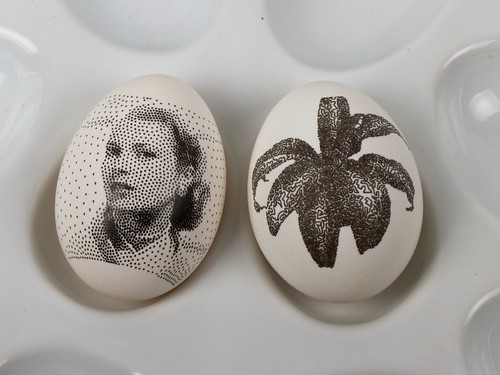
Now, to test our results on some hardware. This file plots in just a couple of minutes on the Eggbot. It’s far from a “traditional” halftone, but it’s still a pretty remarkable result.

StippleGen 2

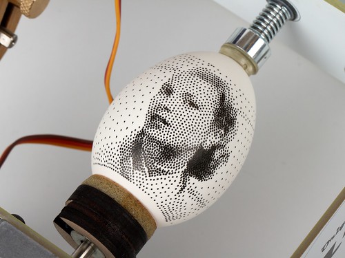
Finally, Grace Kelly graces an egg.

This image is rendered with only 2000 stipples. Properly tuned for making dots rapidly, the Eggbot can plot about four stipples per second, so this kind of a plot can take as little as ten minutes, and can actually produce a remarkable likeness of a photo onto an egg.

Credits and sources 

The StippleGen source code is available as part of the StippleGen .zip file. To run the code from source, you’ll need to download Processing, and install the toxiclibs library and the ControlP5 library.
Much of the “heavy lifting” of our code is really done by the toxiclibs library. This includes the Voronoi cell calculation code, the polygon clipping code, and the code to determine whether or not a given point is within a given polygon. We were able to replace a number of complicated functions that we had written with simple library calls, without loss in performance. This is superbly useful software.

Our code also uses the excellent ControlP5 library for the GUI elements.

Thanks also to Dan Newman for helping calling attention to TSP and stipple art for use in the context of Eggbot, and particularly for documenting it on our wiki.


Additional inspiration:

• Stipple Cam from Jim Bumgardner. Our first stipple drawing code in Processing was based on this project.

• MeshLibDemo.pde A demo of Lee Byron’s Mesh library, by
Marius Watz.


UPDATE: StippleGen 2 has been released, with new features and documentation. Read all about it here!

Modkit Micro on Kickstarter

$
0
0
modkit

Our friends at Modkit are running a new Kickstarter campaign for their excellent Modkit Micro software.


[... ] Microcontrollers are no longer just for engineers — anyone can now pick up an Arduino board at their local Radioshack! Now that microcontrollers are even easier to find and buy, they should be just as easy to interact with and program. Modkit Micro works to make microcontrollers accessible to anyone, regardless of their particular background or skill set.


Modkit Micro is a graphical programming environment for microcontrollers that supports a growing number of popular microcontroller platforms including Arduino and Wiring boards. It makes it easy for almost anyone (perhaps especially those with no programming background) to get started using microcontrollers, just by dragging and dropping blocks on their screen to write the firmware.

That part is already pretty neat, but what's really great about Modkit is that it isn't trying to be a substitute for "real" programming in source code. When you're ready to go deeper, Modkit allows you to go "under the hood" to directly view and edit the code that it generated for you. If you'd like early access to try out Modkit, we'd encourage you to support their project— they're opening up the next round of access to supporters this month.


Link: Modkit Micro on Kickstarter Continue reading

StippleGen 2

$
0
0

StippleGen 5

Two months ago, we introduced StippleGen, a program that can generate stipple diagrams and “TSP path” art from images, using Adrian Secord’s algorithm of weighted Voronoi stippling.  It’s a great (and free) tool for turning a photo into CNC-ready artwork, for use on the Eggbot or in other contexts.

twain5kw-newframe

Today we’re announcing a new verison, StippleGen 2. As with the earlier version, StippleGen 2 is free and open source software, written in the Processing development environment. It comes ready to run on Mac, Windows, and Linux, and it is available for download now.

StippleGen 2 comes with three new features: A gently redesigned set of controls that makes life easier on tiny laptop screens, an inverse color scheme— as illustrated above —so that you can now calculate white stipples on a black background, and comprehensive documentation on our Wiki.

newgui

The controls in StippleGen 2 have been redesigned and streamlined. They are also overall a bit thinner so that the full screen (and all of the controls) can now be viewed on an 11″ MacBook Air, without reducing the size of the main display area.

rembrant2kw

In the first version of StippleGen, the image was always computed with black dots on a white background. For most images that have a light-colored background, this is a good choice.  However, if you have an image with a dark background, you may find that nearly all of your stipples are used to just darken the backdrop, leaving less detail available in the foreground of the image.

StippleGen 2 gives you the option to draw with black stipples on a white background or white stipples on a black background. By using a dark background here, you may be able to recognize Rembrandt in just 2000 white stipples.

rembrant10kwhite

It does, of course, look better with a larger number of points.

apollow10kblackapollow10kw-newframe3

For images with a lot of black and a lot of white, it can be hard to choose which is the better scheme.

However, as this is tool to generate applied artwork, the choice is often made for you in advance.  If you are drawing with a black pen on a white egg, you’ll want black stipples.  On the other hand, if you’re carving into a black panel, white stipples might be the better choice.


hopper7600w
starry10kw

And here are a couple of other “test images” that we’ve been running in the new color scheme.

plant10k_vor

And finally, we have written up comprehensive documentation for StippleGen 2, hosted on the Evil Mad Science Wiki.

StippleGen 2 is free and open source software, now available for download here.
Go try it out for yourself!

StippleGen and a low-power DIY laser cutter

$
0
0

Jens demonstrates using StippleGen2 with his low-power (300 mW!) DIY laser cutter and a classic image of Louis Armstrong.

After letting StippleGen2 crunch the numbers for a while I imported the resulting vector graphic file into inkscape and generated the G-code so that I could use my laser cutter to cut the image into a black paper. 2 hours and 23 minutes later I had a 20×20 cm piece of paper with about a 1000 holes in it and it looks awesome! Would be perfect for a lamp shade or just nice to put up in a window and let the sun shine through. I can highly recommend StippleGen2 it’s super easy and a lot of fun.

A WaterColorBot Water Clock

$
0
0

watercolorclock_1

We built a evaporating-hand water clock using a WaterColorBot fitted with a Buddha Board. The Buddha Board is a black board with a gray ceramic coating that becomes transparent when wet, so you can paint on it with plain water to make black marks that disappear as the water evaporates.  (And, it fits nicely in a WaterColorBot with the appropriate jig.)

watercolorclock_2watercolorclock_3

As a clock, once a minute it draws the minute hand, then the hour hand, and finally the outline of the clock face.

watercolorclock_4

As the water evaporates over the course of a few minutes, the old minute hands fade away. It’s a neat effect.

And of course, video:


For the future, it’s also worth considering a digital water clock, maybe using the fonts from Hershey Text. Its straightforward to write the code, but a legitimate concern is how readable it will be. With the “analog” clock face, the fading minutes make perfect sense. But two numbers written on top of each other might be less legible. Perhaps it should use numbers written in different locations around the board?  If so, we’re going to need a smaller brush.

A separate question is how practical is the Buddha Board as a long-term clock substrate?  Our best guess is “not very.”  After maybe 12 hours of total running time, we can already see some surface change to the Buddha Board, in the constantly-repeated outer circle. The Buddha Board isn’t really designed to handle a robot painting the exact same thing day in and day out.  Moving the clock position slightly might fix the issue (like an old-school screen saver!), or perhaps it’s worth thinking about water painting on slate instead.

watercolorclock_5

The application RoboPaint Clock BB and source code are available on github.

Special Thanks to Vikram D. for the project idea!


Hershey Text JS

$
0
0

Hershey Text JS

James “techninja” Todd has just released Hershey Text JS, a port of the Hershey fonts to JSON, capable of being rendered quickly via JavaScript & SVG.

The Hershey fonts a classic set of “engraving” or “stroke based” (as opposed to outline based) fonts that are excellent for use with all kinds of physical cutting, drawing, and painting machines. Several years ago we introduced the Hershey Text extension for Inkscape, and you can find a more in depth introduction to the Hershey fonts in that article.  Hershey Text JS is adapted from our Inkscape extension, and provides easy access to the font data for programmers who prefer to work in javascript.

The Incredible Computer-Controlled … Computer!

$
0
0

wcb-surface 7

A guest post by Daniel Gentleman 

About a year ago, I started working on a project that used robotics to control a Surface Pro tablet. Not long after I started, I got my first glimpse at the the WaterColorBot on display at Maker Faire Bay Area 2013. The WaterColorBot is designed to carry a paintbrush over a piece of paper, raising and lowering it as needed to paint a picture. The movement and software control is similar to CNC router with special design modifications to make it lighter, cheaper and easier to control. A CNC router has to move heavyweight cutting bit with friction so needs expensive motors, rails, and belts. The WaterColorBot, on the other hand, needs only to move a paintbrush in a low friction environment.

I was instantly sold on the idea of using a WaterColorBot to control the Surface. I backed the Kickstarter, waited for my bot to arrive, and started working on software. When the WaterColorBot arrived, I was not disappointed. The assembly was quick and I was robotically painting in no time.

With the big mechanical and electronic solutions solved, my attention turned to the tablet. The Surface Pro is rare among tablets in that it uses a digitizer that allows extremely precise tracking with a stylus along with “hover” and “right-click” functionality. It does not need to be electrically grounded like a stylus for a screen that only supports capacitive touch. I was certain that the Surface Pro was the way to go, but not quite how it was going to be held together. The project was about to take a another serendipitous turn.


wcb-surface 1

The custom-cut spoilboard

At this point, I shared my enthusiasm with Windell and Lenore of Evil Mad Scientist and they gave me a unique offer: Stop by the Evil Mad Scientist shop and together we would make a custom cut spoilboard (lower deck) fitted to mount the Surface Pro 2. Wielding digital calipers and other measurement and software tools, Windell came up with a design that held the tablet firmly and had extra space cut out for the charger, power button, and USB cable.

wcb-surface 2
wcb-surface 3 wcb-surface 4

The area beneath the tablet has a lip and a lower recessed area. This design reduces wobble and makes it look even better. On the topic of machining – I got a few lessons in how larger CNC machines work. Windell showed me some design considerations in software and gave me a safety briefing about the CNC router itself. This thing can cut fast.

After a little sanding, we fitted the tablet, spoilboard, and WaterColorBot together. Having the co-creators of the WaterColorBot with me on this journey was priceless, as we can see from the final assembly. The first spoilboard we cut matched perfectly and the tablet is held firmly in place.

wcb-surface 6

With enthusiasm fueled by seeing it all fit together, we decided to tell the WaterColorBot to do some painting. Windell loaded up an example sketch in Inkscape and, with only a minute to calibrate the stylus height, we were drawing!

wcb-surface 7

The software running on the Surface Pro is called FreshPaint and we chose a simple marker tool. In the video, you’ll hear a laughter break where the Surface picked up the floating toolbar in the app and dragged it around the screen.

Given a little time, we could have taught the WaterColorBot to change brushes and colors in FreshPaint, but our goals for the day were met. The light weight and low friction of the Surface stylus is perfectly matched for use on the WaterColorBot. A custom fitted spoilboard means the Surface will always be at the exact same place on the X/Y plane, greatly simplifying future software development. Next project: Teaching the robot how to see!

wcb-surface 8
(Full disclosure: My day job is Systems Operations with Yammer, a Microsoft company. This project and use of the Surface Pro 2 is not affiliated with Microsoft in any way nor did they influence the project with sponsorship or exercise any editorial control. If they had, I’d try to talk them into contributing a Surface Pro 3! “Surface” is a trademark of Microsoft Corporation.)
 

DIY Snowflake Chocolate Molds with the Othermill

$
0
0

Our friends at Other Machine Co. have put out a mold making kit for the Othermill and posted an instructable for making snowflake chocolates using the online Snowflake Generator that Paul Kaplan of Inventables ported from our Vector Snowflake Application.

The process involves milling a wax positive for making a silicone mold. The beautiful two-tone chocolates are made by putting white couverture chocolate into the details of the mold, and then filling the rest of the mold with dark.

One more technique we could have used for Operation: CNC Snowflake!

Digi-Comp II replica in Terraria

$
0
0

YouTube user Richard Lewis built a working replica of the Digi-Comp II mechanical computer in the sandbox video game Terraria.

The replica makes extensive use of the so-called “Hoik glitch” in the game, that allows for rapid, controlled player movement, much like gravity guides the balls downward in the original.

More information about the version in Terraria is posted on the video page.

Inkscape version 0.91

$
0
0

A new version of our favorite vector graphics software, Inkscape, was just released! It’s faster and better than ever.

We’re particularly excited because Windell’s Hershey Text extension for rendering stroke-based engraving fonts is now in the set of included extensions.

More CNC Stipple Art

Meggy Jr RGB + WaterColorBot


Politicians To Poop: A Chrome extension

$
0
0

Politicians To Poop

Politicians To Poop is a new extension for the Chrome web browser that replaces the names of presidential candidates (US, 2016) with the “pile-of-poo” emoji. Options allow you to “poopify” the names of Democrats, Republicans, or both.

Politicians To Poop is available now, for free, at the Chrome web store.

Screenshots:

Politicians To Poop

Politicians To Poop

Politicians To Poop

Applications:
Possible reasons that you might want to use this extension include:

  • You are from outside the US, and don’t need to hear these names every day.
  • You are temporarily overloaded by the amount of poop that the candidates sling at one another.
  • Because it is funny.

No judgement upon any of the named individuals, nor their platforms, parties, or beliefs is either implied or intended. This is intended to be an equal-opportunity text replacement tool, for the good of all humanity.

More information:
This project was inspired by Millennials to Snake People. Much more information including source code, the list of names, and additional attribution is available at our GitHub repository.

Game of Life at the Hill Country Science Mill

Hilbert Curve Cat

$
0
0

Shy wrote in to tell us about a tool he created to generate Hilbert curves from images for plotting called Image2Hilbert. (Main GitHub project link, here: )

Shy says:

I added a calculation in the interface and this line is approximately 35.881 meters long and it took about 45 minutes to draw.

Thank you, Shy, for sharing this tool! We look forward to seeing what people make with it.

Holiday Cards with AxiDraw

$
0
0

Pitch Interactive, a data visualization studio, sent out “Happy Holidata” cards made using the AxiDraw.

This year’s card features a snowflake that uses two data points in its generation: how long we’ve known the recipient and the air quality where we’re sending the card. It is unique to the person we sent it to, and no two snowflakes are alike.

After getting some inspiration from dozens of photos of snowflakes, we brainstormed about the different types of symmetry and shapes that would make our design. We then generated the snowflake with a script that draws a certain number of radial spikes based on how long we’ve known the person we were sending them to. Other parameters for the generation rely on random numbers, ensuring that each generated snowflake was completely unique.

They’ve published the code on github, as well as a set of svg files.

Stippled Ceramics

Viewing all 32 articles
Browse latest View live